A clock that looks cyberpunk
I’ve always liked clocks, I’ve actually done a lot of work to find ways to represent time. From Arthur Ganson style clocks that I made back in high-school (Where a gear reduction is used to note time going from seconds to tens of decades) I’ve liked finding ways to represent time in a way that is not the usual.
This is actually my most “traditional” clock piece so far, in the sense that it means to give you the time at a glance, hours and minutes; that’s it. The element that makes this clock different from others is the fact that it pretends to show otherwise hidden elements that a digital clock has, it pretends to show its circuitry, to show off it’s bulky THT resistors and for it to be crude and very interesting to anyone with the knack.
Tags
Clocks
Design Work
The design rationale
The main objective of this first attempt at the “klok” (Named after the Niederlandisch word for “clock”) was simple: embrace rawness.
- Do not hide the elements that make up the PCB, show it proudly.
- The depth of elements must not be hidden, a protuberant arduino nano or THT resistors give it depth.
- Frame it, don’t change it. Give the PCB a unique outline shape, and adjust the frame accordingly, scape from simple rectangles and bricks.

The electronics selection

The selection here was pretty simple, but with a huge flaw in hindsight. We’ll get there.
We have electronics composed of:
- Arduino Nano
- MAX 7219 MuX for 7-segment display management
- A simple piezzo-buzzer for the “Alarm” functionality that makes this fit into thec ategory of Alarm Clock.
- The common Anode four digit seven segment display.
- Five Switches (SW-1 to SW-5) that are laid on a cross like configuration of the PCB. All with their pulldown resistors (software debounced)
- A photoresistor with its corresponding voltage divider resistor setup.
- Lastly, we have TWO jst connector headers:
- J1 was meant to feed the arduino and circuitry from an external 1S-LiPO batteryu and BMS
- J2 was meant to be the I2C communciation port to connect it to the RTC module, since the arduino is unable to keep track of time on its own (precisely, at least).
This is where it goes wrong
J2 was meant to be the I2C communciation port to connect it to the RTC module…
I have to preface by saying this, this one was my third densely populated two-layer PCB. That means that by this point I hadn’t heard of teardrops and other good practices, I send this board to be manufactured in a Colombian shop and that was the first of my mistakes. You see, acid traps plus large manufacturing tolerances make horrible paths and connection reliability.
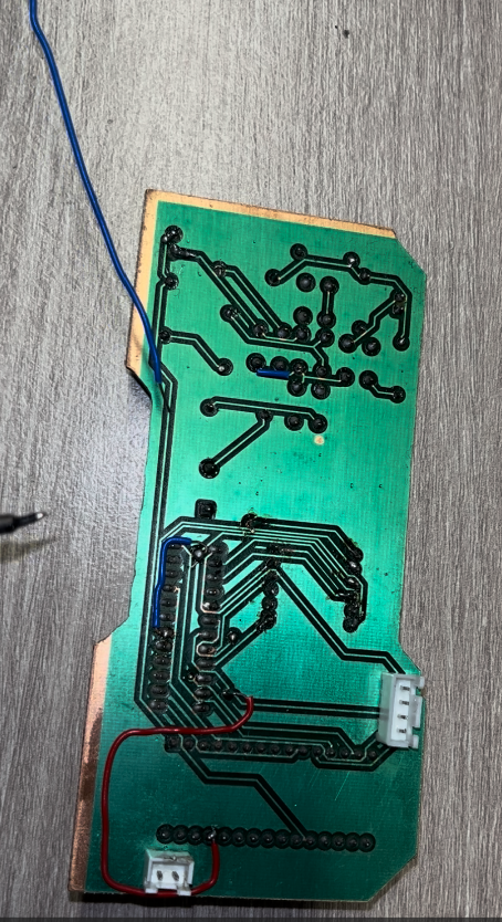
The J2 connector is unconnected. Fully unconnected. From SDA, SCL, power and Ground. So the clock doesn’t know how to clock.
Furthermore, we have an unknown and sneaky connection error with the last digit of the display (minute digit), so while testing it looks like so:
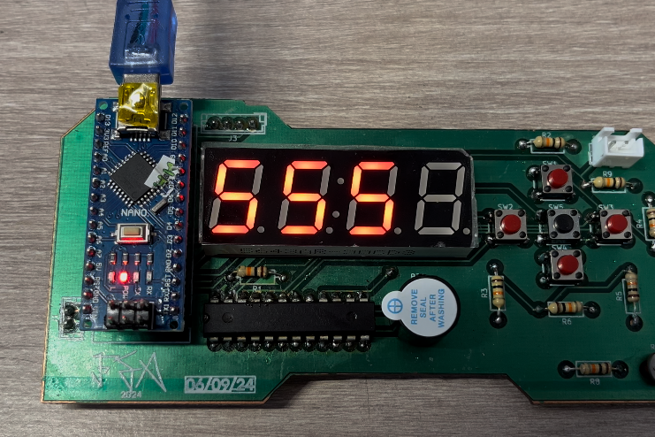
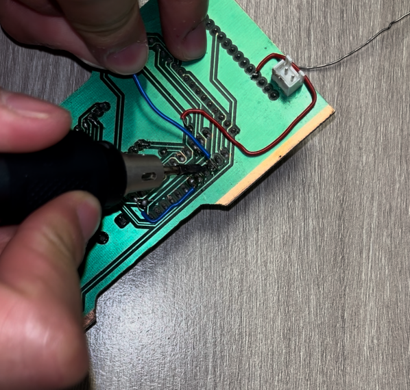
I call the error sneaky because it doesn’t seem to be solved with jumping the “load” trace for that digit registers, as seen in the image below that was attempted:
The clock conceptually is there
We have all the nice Quality of Life features down to the dimming of the screen possible through PWM with the MAX multiplexer, we have the RTC module that uses the I2C connections in the order they are laid out, and we have all three out of four connections working. Yet the fact that even when I attempted to bridge the connections from the Arduino to the MAX, meter for continuity and attempt to bridge to the display means that either:
- The PCB has one trace that grounds/pulls high so badly on one of the MAX’s inputs that it will never update that last digit (I would need tot test each and every single one of them).
- I had / caused / proqued a shot circuit that killed just enough of the MAX that that digit’s output’s are simply cooked.
I will come back to revisit this design
I love the look of a raw alarm clock, but it’s time intensive (Pun intended).
On V2 which will come eventually:
- We are not using an arduino. (If I had used an ESP32 the RTC JST connector being broken wouldn’t have been an issue as I could’ve just pulled the time regularly from a local RTC server and update to prevent overflows and other possible time-keeping issues).
- On that note: We would probably just update the time a couple of times a day via Wi-Fi, saving us the RTC space.
- We are using better routing, teardrops and clear techniques of routing now that we know better.
- We are putting the MAX on a cradle (not being able to remove this suspicious 32 pin chip was one of the main reasons that I had to surrender to this PCB).
- We must consider power input (5V for LEDs 3.3 V for SOC) and place it’s input(s) where it makes more mechanical sense given a new enclosure.
Having said that, there is still a GitHub repo which you can check out:
Thanks for reading me.